Rust Ray Tracer & SDF Engine
A ray tracer written in Rust, capable of rendering Constructive Solid Geometry (CSG).
Unlike using triangle meshes, this engine is a Ray Marcher using Signed Distance Fields (SDFs). This allows for:
- Infinite Resolution: Shapes are defined by mathematical formulas. Curved surfaces (spheres, cylinders) are perfect, not made of polygons.
- CSG Modeling: Real-time Boolean operations (Union, Subtract, Intersect).
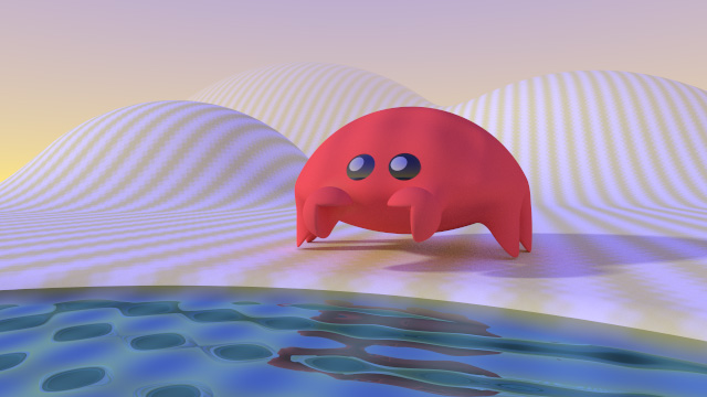
- Smooth Object Blending: Objects can "melt" into each other organically.
- Soft Shadows: Realistic penumbra calculation comes 'for free' with SDFs.
Ray Tracer Instructions
Modify the scene by typing into the scene editor box.
1. Global Settings
The following details relate to the initial values that can be edited.
Rendering resolution
You can change the output resolution, and the sampling quality.
- Width: How many columns of pixels make up the image.
- Height: How many rows of pixels make up the image.
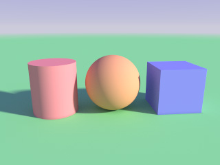
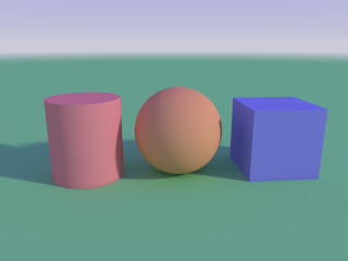
- Samples: Each pixel can be further subdivided into a grid. The value here is the number of both the columns and rows. For example, a value of 4 would use a 4 by 4 grid for 16 samples that are averaged together to make a final pixel colour at the end. Higher values increase the visual quality but also increase the render time.
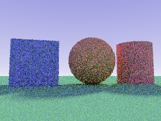 Samples = 1
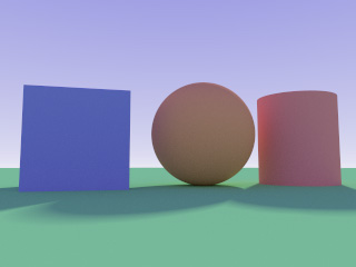 Samples = 32
"render": {
        "width": 640,   // 640 pixels across
        "height": 480,  // 480 pixels high
        "samples": 2    // each final pixel colour is made from 4 (2 by 2) subpixels
        }
Sky (background)
These values change the colours of the sky, the horizon, and also affect the mist/fog that forms in the far distance. Both are RGB (Red Green Blue) values.
- Horizon: The colour in the distance where the height value is zero.
- Zenith: The colour directly above. Between the horizon and zenith, the colours will be blended to form a gradient.
 A red horizon with a purple sky.
"sky": {
        "horizon": [0.8, 0.8, 1.0], // A pale blue horzizon
        "zenith": [0.0, 0.0, 1.0]   // A deep blue sky above
        }
Camera Control
You can move the camera anywhere in 3D space.
- Position: Where the camera is located
[x, y, z]. - Look At: The point the camera is focused on.
- FOV: Field of View in degrees. Higher values (e.g., 90.0) create a wide-angle lens effect.
 This animation was made by changing the x position of the camera.
"camera": {
        "position": [0.0, 5.0, 10.0], // High up and pulled back
        "look_at": [0.0, 0.0, 0.0],   // Looking at the center
        "fov": 45.0
        }
Lighting (brightness)
To change the scene brightness, adjust the intensity value.
- Direction: and xyz vector. The direction can be thought of as an arrow that starts at this value as if it is a position, and the arrow points to the centre (0,0,0).
- Values:
1.0is standard. Lower values (0.5) are dim, higher values (2.0+) create overexposed/bright scenes.
 Intensity of 1.5
 Intensity of 0.5
"light": {
        "direction": [4.0, 2.0, 2.0], // The light comes from the right, above and in front of the scene.
        "intensity": 1.0
        }
2. Creating Objects
Objects are defined in the objects list. The renderer processes this list in order (see "The Stack Logic" below).
Common Properties
Every object shares these fields:
- color: RGB values from
0.0to1.0.[1.0, 0.0, 0.0]is Red. - reflectivity:
0.0is matte (diffuse),1.0is a perfect mirror. - texture_type:
"Solid","Bumpy","Streaky"or"Checkered".
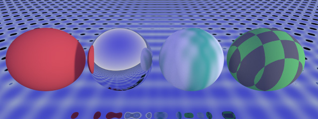 The ground plane uses 1.0 reflectivity and the Bumpy texture. The first sphere uses Solid. The second is Solid with 1.0 reflectivity. The third uses Streaky. The last uses Checkered.
Sphere
Defined by a single radius parameter.
{
        "primitive": "Sphere",
        "position": [0.0, 1.0, 0.0],   // The centre of the sphere is a bit above the centre of the scene
        "parameters": [1.0],           // The total height and width of a sphere will be double the radius
        "color": [1.0, 0.1, 0.1],      // Red
        "reflectivity": 0.5,           // Partially reflective
        "texture_type": "Solid"        // Colour only, no pattern
        }
Cube
Defined by "half-extents" (distance from center to edge).
- Parameters:
[x_radius, y_radius, z_radius] - Example:
[1.0, 1.0, 1.0]creates a cube that is 2 units wide, tall and deep.
{
        "primitive": "Cube",
        "position": [2.0, 0.5, 0.0],   // To the right, and a bit above the centre
        "parameters": [0.7, 0.7, 0.7], // Size X, Y, Z
        "color": [0.2, 0.2, 1.0],      // Blue
        "reflectivity": 0.0,
        "texture_type": "Solid"
        }
Cylinder
Defined by the total height and the radius.
- Parameters:
[height, radius]
{
        "primitive": "Cylinder",
        "position": [-2.0, 1.0, 0.0], // To the left, and a bit above the centre
        "parameters": [2.0, 0.5],     // Two units tall, diameter of 1
        "color": [0.2, 0.8, 0.2],     // A shade of green
        "reflectivity": 0.2,
        "texture_type": "Solid"
        }
Flat Plane (Floor/Wall)
Defined by a Normal Vector (the direction it faces).
Warning: If a plane's position and parameters are such that the camera would show the reverse side of plane (like if a plane intended to be the ground has a negative y parameter), the scene will be completely dark.
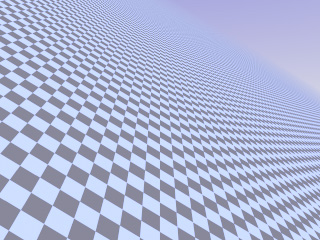 The parameters [0.6, 1.0, 0.5] have tilted the chequered plane.
- Parameters:
[x, y, z]normal vector. [0, 1, 0]= Floor facing up.[0, 0, 1]= Wall facing forward.
{
        "primitive": "Plane",
        "position": [0.0, -1.0, 0.0],  // A bit below the centre
        "parameters": [0.0, 1.0, 0.0], // Normal pointing UP
        "color": [0.8, 0.8, 0.8],      // A light grey
        "reflectivity": 0.1,
        "texture_type": "Checkered"
        }
3. Advanced Modeling: The "Stack" System
This engine uses a unique Stack-based approach to modeling. The scene is built layer-by-layer, starting from empty space. The order of objects in the JSON list matters significantly.
Each object applies an Operation to the world that exists before it in the list.
Operations
"Union": Adds the object to the world. This is the default operation."Subtract": Carves the object shape out of the world."Intersect": Keeps only the area where the object and the world overlap.
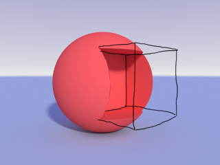 A sphere is cut into by a cube using Subtract.
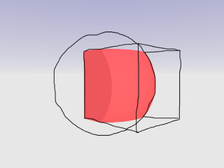 Using Intersect, only the parts of the sphere and cube that overlap are visible. The ground isn't in this area, so it is now gone as well.
Blending (Smooth Transitions)
You can set a blend value (e.g., 0.5) to smooth the transition between the new object and the existing world.
- Smooth Union: Creates organic "blob" shapes.
- Smooth Subtract: Creates soft, rounded holes.
- Smooth Intersect: Creates rounded corners between overlapping shapes.
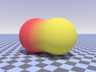 A red sphere and a yellow sphere blended into each other.
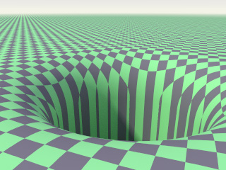 Using Subtract and a high blend value, an invisible cylinder makes a hole in the ground with a rounded edge.
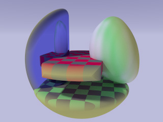 A cube, sphere, cylinder and plane inside an Intersect sphere, which has removed all object parts that are outside of it. Edges are smooth because of blending, and have also adopted the material properties of the sphere.
Important: Preventing Accidental Deletion
If you use Intersect or Subtract, be careful with your ordering.
- If you place an Intersection Cube at the end of the list, it will intersect with everything (Floor, Sphere, etc.). Anything outside that cube will vanish, apart from the sky.
- Tip: If you want a specific intersection shape (like a cube with rounded corners) to sit on a floor, create the intersection shape first, and add the Floor (Union) last.
4. Limitations
There are several common 3D modelling features that are unavailable here.
- Objects cannot rotate: The camera can move around a scene, and the plane can tilt, but otherwise scenes have to be constructed without turning the objects.
- Only one light: The light is defined as a direction rather than a point, and its colour is white only. A view from between parallel planes may result in the whole scene being in shadow.
- No transparent objects: see-through objects and light refraction are not supported.
- Texture properties are fixed: They cannot be resized or rotated.
- Several atmospheric properties are fixed: Fog, draw distance, ambient light, ambient occlusion and global illumination properties cannot be changed or switched off via the editor.